1.5.36
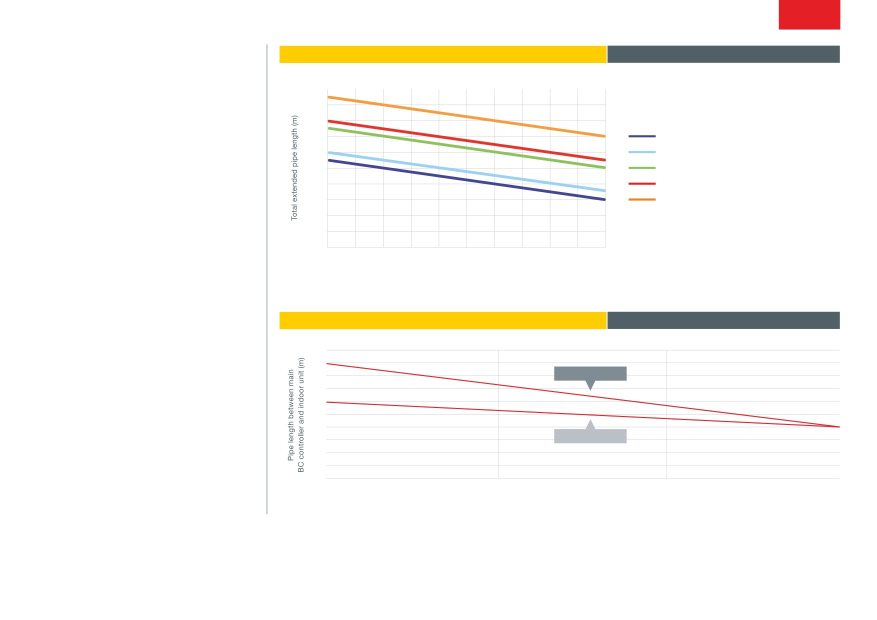
GRAPH 1: TOTAL PIPING LENGTH RESTRICTIONS
R2 Series
Piping Design
1000
900
(R32 & R410A)
800
700
(E)P/(E)M200, 250, 300
600
(E)P350, 400, 450, 500, 550
500
(E)P400, 450, 500, 550, 600
400
(E)P650
300
(E)P700, 750, 800, 850, 900, 950, 1000, 1050, 1100
200
100
0
10
20
30
40
50
60
70
80
90
100
110
distance between outdoor unit and bC controller (m)
GRAPH 2: PIPE LENGTH BETWEEN BC CONTROLLER & INDOOR UNIT
100
90
80
Via sub bC
70
60
50
40
30
No sub bC
20
10
0
0
5
10
15
height difference between the main bC controller and indoor unit (m)
Note: For all other piping restrictions please refer to the City Multi Databook
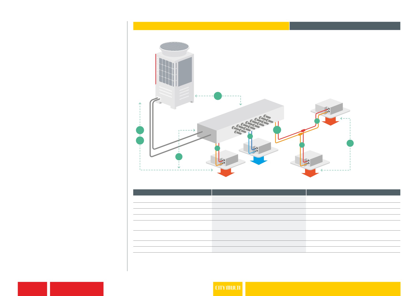
1 BC CONTROLLER, NO SUB BC CONTROLLER
R2 Series
Piping Design
(R32 & R410A)
Outdoor Unit
A
Master BC
d
H
B
b
H’
c
h2
a
h1
h1
PIPE LENGTH
PIPE SECTION
MAX LENGTH
Total piping length
a+b+a+b+c+d
(see graph 1)
furthest piping length
a+b+d
165m
length between OU and bC
a
110m*1
length between furthest iU and bC
b+d
60m*2 (40m)*3
height between OU and iU
h
90m*4
(OU above iU)
,
height between OU and iU
h
60m*2
(OU below iU)
height between iU and bC
h1
15m
height between iU and iU
h2
30m
Notes: *1 Please refer to Graph 1. *2 Height difference between BC controller and furthest indoor unit is zero. Please refer to graph 2. *3 If P200 or P250 indoor unit connected on system. *4 Please contact your sales office for guidance.
please Note: this does not apply to PURY-RP models.
For guidance on applying Sub BC controllers, please contact your sales office.
1.5.37
Air Conditioning
R2 Series Piping Design